¶ Pre-Requisites
Drill Press Training
The goal of this page and the accompanying “training” is not to make you a mill operator/machinist, but to make sure you can safely do certain tasks. It applies to all students, staff, faculty, and others who wish to use the machine shop! This page should be read, fully understood, and reviewed. The allowable machining tasks will be limited to those covered on this page. There is much more to using a mill than what is covered on this page. Always ask before doing a new operation!
¶ Manual Mill Introduction
Milling machines are very versatile. They have usually been used to machine flat surfaces, but can also produce irregular surfaces. They can also be used to drill, bore, cut gears, and produce slots. The type of milling machine most commonly found in student shops is a vertical spindle machine with a swiveling head. Although there are several other types of milling machines, this document will focus only on the vertical milling machine.
A milling machine removes metal by rotating a multi-toothed cutter that is fed into the moving workpiece. The spindle can be fed up and down with a quill feed lever on the head.
The bed can also be fed in the x, y, and z-axis manually. In this clip the z-axis is adjusted first, then the y-axis, then the x.

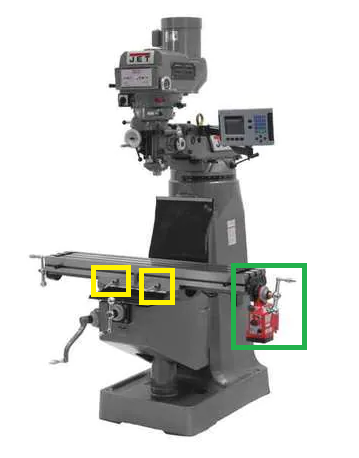
Once an axis is located at the desired position and will no longer be fed, it should be locked into position with the Gibb locks (Yellow, Fig 2).
Most milling machines are equipped with a power feed for one or more axis. Power feed is smoother than manual feed and, therefore, can produce a better surface finish. Power feed also reduces operator fatigue on long cuts. On some machines, the power feed is controlled by a forward-reverse lever and a speed control knob (Green, Fig 2).
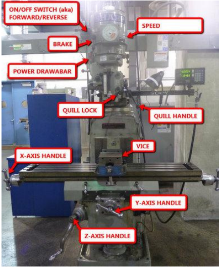
ON / OFF SWITCH: For turning the spindle ON or OFF and for changing the direction of spindle rotation.
BRAKE: For manually stopping the rotation of the spindle after turning the spindle off.
SPEED KNOB: For adjusting the spindle rotation speed (RPM)
POWER DRAWBAR: For inserting or removing collets/cutters from the machine spindle.
QUILL LOCK: For locking the machine’s quill at a preset height or location.
QUILL HANDLE: For moving the quill up and down in the Z-axis direction.
VICE: For clamping workpieces onto the milling machine table.
X-AXIS HANDLE: For moving the machine table in the X+ or X- direction (left or right)
Y-AXIS HANDLE: For moving the machine table in the Y+ or Y- direction (front to back)
Z-AXIS HANDLE: For moving the machine table in the Z+ or Z- direction (up and down)
¶ Machine Set-Up
¶ Tramming the Head
The head of a vertical milling machine can be tilted from side to side and from front to back. This allows for the versatility of the machine, but these adjustments can drift. Occasionally, one should check and adjust the head so that the spindle will be normal to the plane of the table. Install a dial indicator into the spindle so that the dial is offset at least six inches from the axis of the spindle and the indicator probe is facing down. Lower the spindle until the dial indicator contacts the table then registers about one-half of a revolution. Set the dial indicator is toward you and set the bezel to zero. Rotate the spindle by hand 180 degrees. If the dial indicator still reads zero, the spindle is aligned front to back. If not, adjust the head until the dial reads half of the original reading and iterate the entire process until the error falls within acceptable limits. Repeat the process with the dial displaced left and right to alight the head side to side.
¶ Squaring the Vise
Work on a milling machine is most often held in a vise clamped onto the bed. To make features aligned with the edges of the stock, it's necessary to align the vise with the feed axes of the mill. To do this, mount the vise on the bed and secure it with T-bolts, but only lightly so as to permit adjustment of the orientation of the vise. Mount a dial indicator in the spindle of the machine with the probe facing away from you. Lower the spindle and run the bed of the table back until the fixed jaw of the vise is in contact with the indicator and further until the indicator registers one-half of a revolution. Set the bezel to zero. Use the cross feed to run the indicator across the face of the vise. If the vise is squared, the indicator will remain at zero. If the dial indicator does not read zero, tap lightly with a soft hammer to realign the vise reduce the indicator reading to half of its previous value. Iterate this procedure until the dial indicator reads zero through the full travel across the face of the vise. Tighten down the T-bolts be careful not to change the vise orientation. Recheck the alignment of the vise.
¶ Setting Spindle Speed & High/Low Gearing
Spindle speed is set by turning the speed crank on the right side of the spindle. The spindle must be on and rotating to adjust the speed. There is a manual display (dial) on the head of the machine that shows the speed in rpm. The spindle speed dial has two scales, one for low range, and one for high range. The machine is switched between ranges with “SPEED RANGE” lever on the right side of the machine head. Switching this lever must be done with the spindle not running! Sometimes, the spindle must be rotated slightly (by hand) to allow the gears to mate properly and allow the lever to “click” into gear.
¶ Using an Edge Finder
Before doing precise work on a milling machine, one must locate the edges of a part accurately. An edge finder is designed to do this on edges with flat vertical surfaces. An edge finder is composed of two concentric cylinders, spring-loaded together. To use it you must first insert it into the machine with the appropriate collet. The big end of the edge finder is held in the collet at least ½ way in. Start the spindle and set the speed to approximately 1,000 RPM. Flick the bottom of the edge finder to induce a wobble in the smaller diameter. The smaller diameter is usually 0.200” diameter. Then, move the part into the tool very slowly. The edge finder will center up, then break out of concentricity suddenly. At that point, reset the dial indicator or digital readout for that axis of the machine to a value equal to the radius of the edge finder. Repeat the process at least twice to make sure your edge finding was correct.
¶ Digital Read-Outs
The mills are equipped with an electronic display for accurate positioning. These DROs have a 4 place display (.0002” accuracy) for the X and Y axes. The Z axes are still read off the mechanical dial on the Z-axis handle with a .001” accuracy. There are two systems of measurement that the DROs can supply, Incremental and Absolute. Absolute should be used for the “zero” corner of your part and not be changed during the job. The incremental setting can be “zeroed” as necessary for use between any two locations, features, holes, etc.
¶ Cutting Fluids
Different applications and/or materials require slightly different cutting fluids. These fluids are designed to provide the correct amount of lubricity, cooling, better surface finish, increased tool life, and more. All cutting fluids (especially WS11) should be thoroughly cleaned/removed from the machine when finished! The machine should be dry and a light “misting” of WD40 applied to the entire vice, tables, and machine ways to prevent corrosion.
Fluids
- WS11 – Water soluble oil. A combination of 5% WS11 oil + 95% water. Resembles “milk”
- A9 Cutting Fluid. Specially designed for aluminum and other soft metals. Green in color.
- MolyDee. A thick, black, heavy cutting fluid for steels and other tough-to-machine materials.
- WD40. Not a cutting fluid, only use to protect against corrosion on cleaned machines.
Applications
- Aluminum & other soft materials tapping: Use A9 cutting fluid. Applied with a drip from the nozzle or brushed onto the tap.
- Aluminum & other soft materials drilling/milling/boring/etc: Apply liberal amounts of WS11 with an acid brush or spray bottle
- Plastics: Most do not need any cutting fluids. Correct speeds & feeds are more critical.
¶ Cleaning the Machine
The entire machine must be cleaned after every use. If another user needs the machine, immediately after you, make sure you discuss who will leave the machine clean. The process is simple and should not take more than 10 minutes. Make sure you are aware of the clock to leave enough time to finish clean-up. The procedure is:
A. Turn off the machine and remove the cutter and collet from the spindle.
B. Put away all your hands, set-up, and cutting tools. If not sure where they go, ask a mentor.
C. Use a brush or light blasts of air to remove the chips from the vice, table, and ways.
D. Do not blast the chips and fluids across the shop, use enough force to get the chips to the ground.
E. Brush or vacuum the difficult-to-reach spots. Wipe the spindle, table, ways, covers, vice, etc…
F. Wipe off ALL cutting fluids and oils from the ENTIRE machine. Top to bottom, the machine must be dry.
G. Gently mist the table, ways, vices, or chuck(s) with WD40. Pump the central lubrication handle 4x.
H. Sweep the floor and surrounding areas. Chips are to be placed in chip buckets, not regular trash cans.
I. There should be NO visible chips of any size on the machine. Leave it cleaner than when you found it.
¶ Basics of Cutting
¶ Climb and Conventional Milling
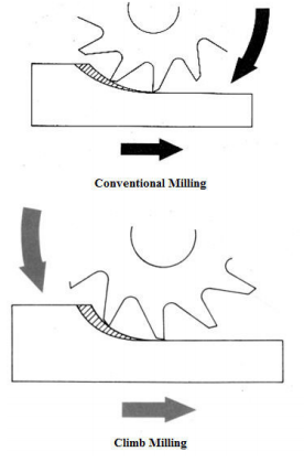
This section refers to using end mills (or similar tools) and cutting away at the side/wall of a workpiece. When milling, one should be aware of the difference between conventional and climb milling. In conventional milling, the workpiece is fed against the rotation of the cutter. The material is being scooped away. This type of cut has lower forces and is preferred for roughing or heavy cuts. It should be used in most cases. In climb milling, the work moves with the rotation of the cutter, as if it is “climbing up” the material. Using a climb cut for a “last pass” or a “finish pass” to remove only .002” - .015” is OK. Using a climb cut for heavy material removal could lead to tool breakage and damaged parts. A Climb cut is normally preferred in our use of the mill.
¶ Drilling
Drilling is the process normally described as cutting round holes in a material. Keyless drill chucks are the most common way to hold drill bits. Bigger drill bits (over .500” dia) can be held in R8 collets ONLY if the drill shank (aka, body) is the EXACT SAME SIZE as the collet being used. Be aware of the range capability of the drill chuck, most are 0.063” to 0.520” The best way to tighten a “keyless” drill chuck is (with the machine OFF) to hold the machine’s spindle brake and turn the chuck body counterclockwise. Reverse this to release the drill bit, but make sure you don’t allow the drill bit to fall out!
¶ Calculating Speeds and Feeds
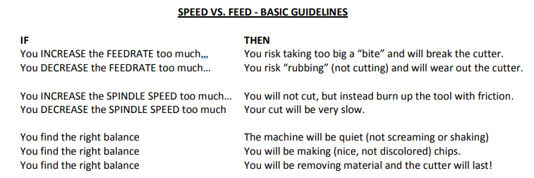
“Speed” refers to the spindle RPM (Revolutions Per Minute). “Feed or feedrate” refers to the amount you make the cutting tool move across or into your workpiece (aka, feedrate). Feeds and speeds affect the time to finish a cut, tool life, finish of the machined surface, and power required of the machine. The cutting speed is mostly determined by the material to be cut and the material of the cutter. Lubricant plays a critical role in cutting. Make sure you use plenty of the correct type! Broken or abused tools are the responsibility of the user and will have to be replaced at your cost. To find the right speed for any task, first, ask a mentor. If unavailable, use the “Speed vs. Feed” guidelines as a starting point. The feed rate depends on the width and depth of cut, finish desired, and many other variables. THE most common mistake is to run the feeds or spindle speed too fast!
¶ Drilling, Boring, and Reaming
Much much more accurate than a drill press
The milling machine may be used effectively for drilling, since the accurate location of the hole may be secured by means of table positioning. Spacing holes in a circular path, such as the holes in an index plate, may be accomplished by indexing with the index head positioned vertically.
Twist drills may be supported in drill chucks fastened in the milling machine spindle or mounted directly in milling machine collets or adapters. The workpiece to be drilled is fastened to the milling machine table by clamps, vises, or angle plates.
For boring, there are various types of boring tool holders that may be used for boring on the milling machine, the boring tools being provided with either straight shanks to be held in chucks and holders or taper shanks to fit collets and adapters. The two attachments most commonly used for boring is the offset boring head, also known as the “Criterion Boring Head”
The single-edge cutting tool used for boring on the milling machine is the same as a lathe cutter bit. Cutting speeds, feeds, and depth of cut should be the same as that prescribed for lathe operations.
Boring is usually used for holes bigger than .500” diameter. The most accurate way to finish a hole smaller than .500” diameter is the process of reaming. Reaming is a process that slightly enlarges a pre-existing hole to a tightly toleranced diameter. A reamer is similar to a mill bit in that it has several cutting edges arranged around a central shaft. Reaming is always done after hole drilling. If the hole is drill crooked, the reamer will follow the crooked hole. Reaming should not be relied upon to correct the location or alignment of a hole. Reamed holes should not intersect with drilled holes. Its primary purpose is to fine-tune the diameter of the hole. Reaming is most accurate for axially symmetric parts produced and reamed on a mill. Reamers come in a multitude of sizes.
¶ Setting Up Material
¶ Using a Vice
A precision vice is the most common way to hold parts in a milling machine. There are several considerations that must be taken into account to make sure the part is secure. At first, you should seek guidance from a mentor for every setup in a vice and learn by example. Vice stops will enable you to accurately take parts in and out of the vice, learn how to use them. Most importantly, always get a mentor's advice for unusual shaped parts or setups. Some general guidelines:
A. ALWAYS SHUT OFF THE MACHINE BEFORE DOING ANYTHING IN OR NEAR A VICE.
B. Don’t assume the vice is aligned or tightened down! Always check with an indicator.
C. Always wipe off the vice jaws, parallels, and other fixtures when clamping a new part. D. Always grip at least 50% of the part and in the center of the jaws.
E. Never grip a part at just one end of the vice, unless an identical part is at the other end.
F. Get instruction or supervision!
¶ Using Parallels
Parallels are used to raise the work above the vice jaws for machining, drilling, or other operations. They can set the part height so the vice jaws will not be hit by your cutting tools and that any drilling operations will not cut into the bottom of the vice. Make sure you use a matching (height) set. Also, be aware of running into the parallels, and constantly check to see that they have not moved unintentionally. It is a good idea to always check that no chips have fallen on top of or underneath the parallels, as this will greatly affect the accuracy of your parts!
¶ Squaring Stock and Face Milling
This is the first step in producing accurate parts.
To create a square corner on a part, first orient an already finished edge vertically in the vise and clamp lightly onto the part. Set a machinist's square against the finished edge and the bottom of the vise. Lightly tap the part with a plastic hammer to align it with the square. Clamp the vise down securely. Now the top edge of the part is ready to be milled to horizontal.
It is often necessary to create a flat face on a large part. This is called face milling. Select a sharp, flat bottom, end mill cutter a little wider than the workpiece so that the facing can be accomplished in one pass. This can work for end mills up to .750” diameter in size. Beyond that size, you will have to make multiple passes or use a flycutter.
Fly cutting, which is also called single-point milling, is one of the most versatile milling operations. It is done with a single-point cutting tool shaped like a lathe tool bit. It is held and rotated by a fly cutter arbor. You can grind this cutter to almost any form that you need. It is more economical to grind the desired form on a lathe-type tool bit than to buy a pre-ground form cutter, which is very expensive and usually suitable only for one particular job.
For milling slots, end mills are an ideal tool. They will produce a slot within two one-thousandths of an inch in one pass. If greater accuracy is required, use an end mill a little smaller than the desired slot. Measure the slot you produced and then open it to the desired dimension with a second pass. Note that the depth of the cut should not exceed three times the diameter of the cutter.
¶ Other ‘Stuff’
Never be afraid to ask for help and guidance, that is why the mentors are there! When in doubt, always ask!
These are very capable machines, but must be used correctly to avoid damage and accidents. Learn how to use them correctly, there are no shortcuts in quality and safety!
Come prepared. Have your material/parts, complete (accurate) drawing(s), a plan of action, and a list of tools you will need.
Cutting tools are expensive and easy to break or dull.
Don’t leave rags, measuring, or other precision tools on the table of the machine. They will get damaged, contaminated, or fall off.
Double-check your setup before starting any operation. Check for tightness/rigidity, correct speeds/feeds, obstructions, clamps, etc.
Re-read the safety rules, your life and health depend on it!
¶ Skill Verification
- Square a Vice
- Identify Parts of the Mill (Items listed in Figs 1, 2 & 3)
- Set Zero Points With DRO
- Use Edge Finder to Zero an Edge
- Face a Block of Material
- Swap and Add Tooling
- Collets
- Drill Chuck
- Haimer
- Turn on Machine
- Get Spindle To Spin
- Change Spindle Speed
¶ Quiz