¶ Introduction
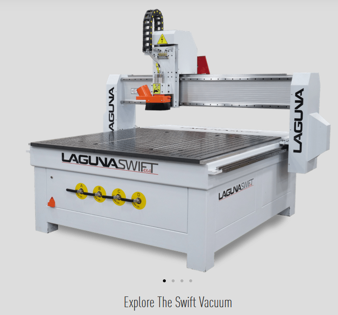
The CNC router is one of the most important tools we have in our shop. We will have two Laguna routers, the Swift and IQ. The Swift has a larger work envelope, as well as a vacuum fixturing system. The IQ will be outfitted with a tube jig for routering box tub. Their primary use case is cutting large sheets of aluminum or polycarb, and eventually box tube.
We also use a software called Vcarve to generate the Gcode required by the machine to run. In short, Gcode is the programming language for the machine (the same language as the 3D printers). These instructions tell the spindle where to move and when, to trace out the cuts that the machine needs to do.
Operation of the CNC router can be divided into a few sections:
- Vcarve/GCode
- Fixturing/Spoilboard
- Manual Operation/Control
- Tool Changing/Running a job
Each section is important by itself, and knowledge of all sections is required for safe and effective operation of the machine. As always, safety is of paramount concern. The CNC router is equipped with powerful motors that control it's movement, and they will easily overpower anything that is in the way.
¶ Safety
NEVER put any body parts in the path of any moving parts on the router, ESPECIALLY the spindle. The End mill is spinning at around 18,000 RPM and will easily cut through anything in front of it. While running a job, the machine might also make fast slewing movements in a surprising direction, so be sure to keep all hands clear.
ALWAYS be paying close attention to the machine. Keep close eye on the progress of the job. If the machine does something you did not expect, do not be afraid to stop the job, or worst-case hit the E-stop.
NEVER be more than an arms length away from the hand-held controller, or the E-stop button. In case the material is not properly secured on the work table, it may come loose and damage the tool, or potentially get launched off of the work table into the shop.
LISTEN to the machine. Often times you can hear when something on the machine will go wrong. If the tool is chattering, or the material is vibrating on the work table, it is highly likely something is going wrong. If the material is not properly secured to the spoil board, it can shift up and down, likely damaging or breaking the tool.
¶ Vcarve/Gcode
¶ Introduction
To effectively use the CNC router, the operator must also understand Vcarve. The program itself is intuitive and simple to use. The difficult part is understanding the quirks of the machine and adjusting the settings in Vcarve accordingly. The following video outlines the most important features that we will use in Vcarve.
https://www.youtube.com/watch?v=Ffn1F5D2Mcc

¶ Workspace Setup
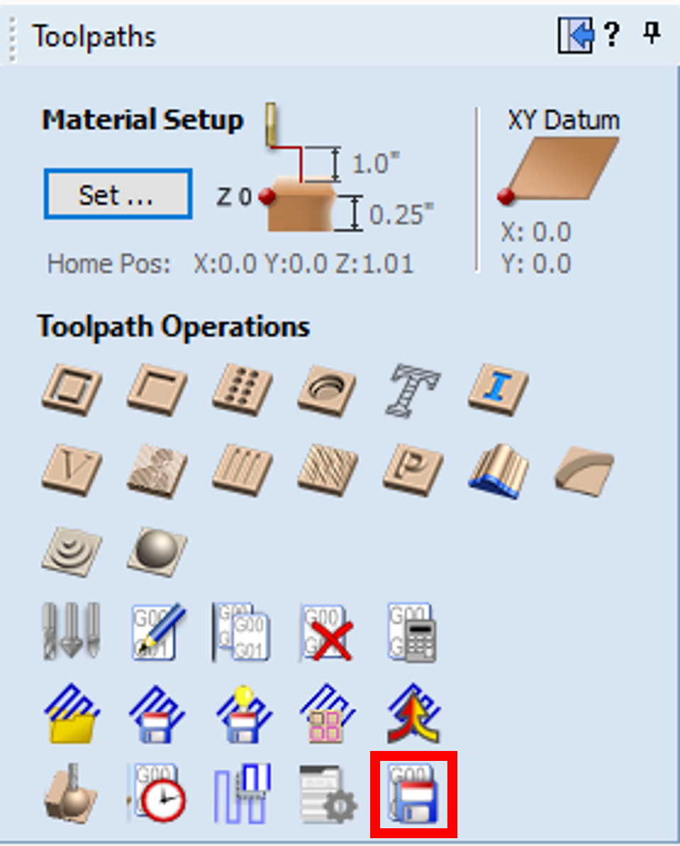
We follow the same setup as the video, regarding Z zero position and XY Datum position of the workspace.
I.e. Z zero on material surface, and XY datum position in the lower left corner.
The best practice is to make the dimensions of the workspace equal to the size of the material that is being cut. This includes all three dimensions (X-Y-Z) of the material, with the Z thickness being the most crucial.
¶ Importing Vectors
The first step to create a toolpath in Vcarve is importing your vectors. In order to get the vectors, you must export the profile of your part from Onshape as a DXF file.
https://www.onshape.com/en/resource-center/tech-tips/tech-tip-importing-and-exporting-dxf-files
To do this, you can right-click either on a face or sketch inside of your Part Studio. The key thing to remember is you must be inside the Part Studio, if you’re in an assembly view then that option won’t be available. Make sure the format is DXF, and the version is the latest version available (release 14 as of late).
Once the DXF is downloaded, you must import it into Vcarve. You can either click on the “Import Vectors” button, or click and drag the file into the workspace.
¶ Joining Vectors
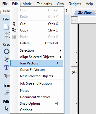
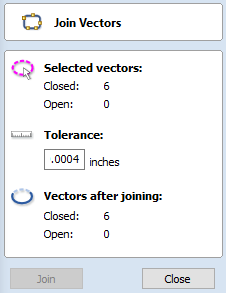
When the Vector file is imported, you must then ‘join’ the vectors. To do this, you must hightlight all vectors, then hit J on your keyboard, or click on the join option under the edit menu-tab. This operation joins the individual vectors that define the inner and outer profiles of you part, and makes it possible for Vcarve to understand the inner and outer faces of your part. This step is important when later creating the toolpaths, as the profile and pocket toolpaths rely on “closed” vectors. If the vectors have not yet been joined, they will be described as “open”.
¶ Creating a Toolpath
Once the vectors are joined, you can create a toolpath.
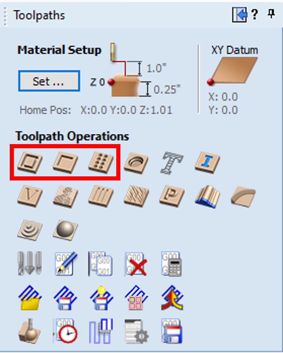
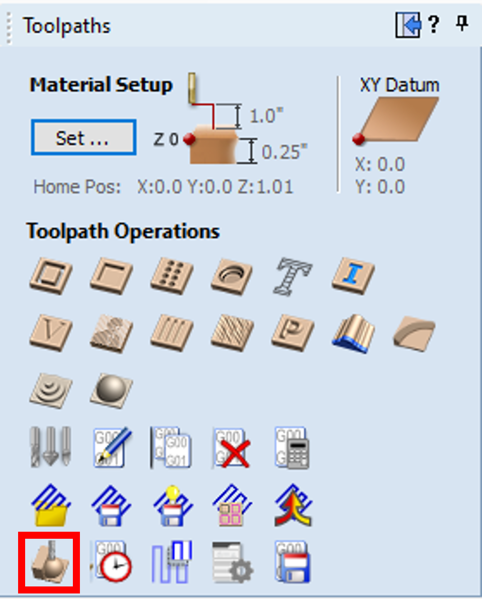
There are 3 types of toolpaths we will generally use: profile, pocket, and drill. To create a toolpath, you open the toolpath menu on the right side of Vcarve, and select the specific toolpath icon.
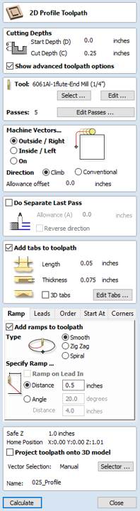
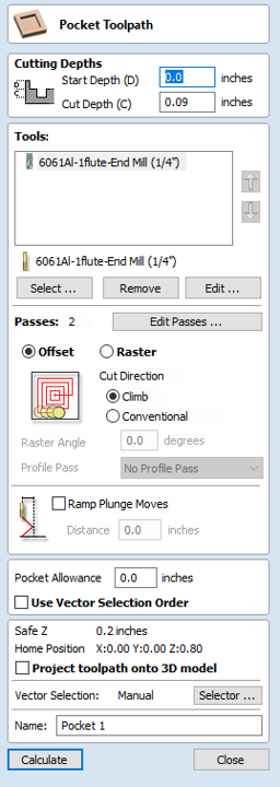
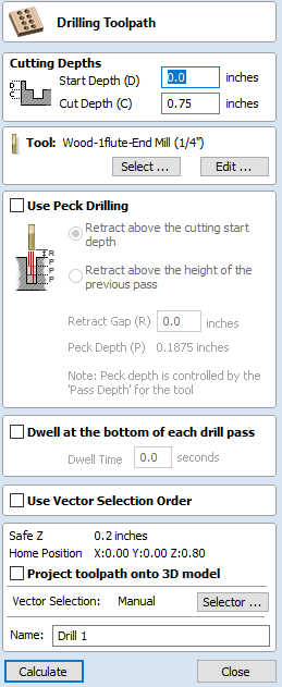
A profile cut follows the outer or inner edge of the selected vector(s), a setting that can be changed in the toolpath settings. A pocket cut follows the inner/outer edge of a selected vector, but instead of only following along the vector, it also will remove any material inside/outside of the selected vector. A drill 'cut' simply plunges the tool at a specific location.
A key difference between a profile and pocket toolpath is that a profile cut will almost always need tabs, to ensure the part does not detach from the sheet of material while the cut is happening, while a pocket cut will not require tabs, as all of the inner material is removed during the operation.
In general, the outside edge of a part will always be a profile cut and will have at least 3 tabs. Obviously that number is variable, and depends on the size and shape of the part. The inside edges of a part will either be included in the profile cut, or will be a separate pocket toolpath. In the wing-rib example, there are only 3 inner pockets, and each one is fairly large relative to the overall part. With few, large inner pockets in the part, a profile cut with tabs would be faster. With many, small inner pockets in the part, a pocket cut is required. If a profile cut with tabs is done on the inner pockets, the operator needs to manually cut the tabs and remove the excess inner material on each pocket. If there are many pockets, this process takes much longer and isn’t worth the effort. Instead, a pocket profile can be done which removes the inside material and doesn’t require any further work (other than the deburring that is required on all cuts).
The first option in the toolpath is Cut Depth. This should almost always be equal to the thickness of the material. Vcarve has a nice shortcut to automatically put the Z height of the material into the cut depth parameters. This can be done by typing “z=” into the cut depth. Sometimes a pocket will not go through the entire thickness of the material (actually living up to the name), so that depth will need to be obtained from the CAD model, or it will be specified in the Jira Ticket.
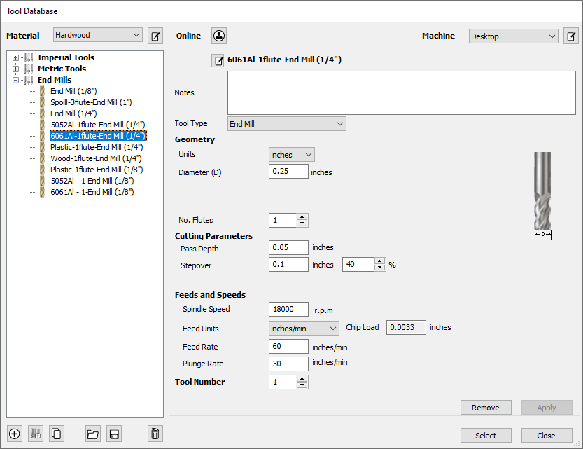
Once the vectors are selected and a type of cut is chosen (profile/pocket), the next step is to choose a specific tool from the “Tool Database”. The tool database includes a list of the specific tooling we have for the routers. The tools we will almost exclusively use are single O-flute end mills, with diameters of 1/8” or 1/4”. We also have some 5mm tools (~0.196”), which would only be used for specific circumstances. For each tool in the database, there are the general properties of the tool itself, and there are associated properties that have been tuned to our machine. The most important tuned properties include Pass Depth, and Feed Rate. These properties may differ based on which material is being cut. For instance, the pass depth and feed rate can be much larger for wood/polycarb than for metal, as wood/polycarb are much softer materials. Also, these values can be different for different alloys of Aluminum (6061 vs 5052).
For a profile cut, the remaining options are Ramp and Tabs. The smooth ramp option should be checked, with the length around 0.5-1.0 inches. Ramping offers an alternative to an ordinary plunge maneuver, where the tool will gradually reach the desired depth of cut. For a smooth ramp, the plunge maneuver takes place over the set length. This means that the tool will travel diagonally downwards by the set 'depth of cut' across the 'ramp distance' specified. The zig-zag ramp will traverse back and forth along a set distance to reach the desired DOC. A spiral ramp will use the entire length of the profile to reach the desired DOC.
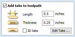
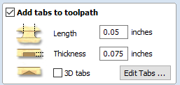
Tabs are also very important. As stated earlier, tabs help prevent the cut part from detaching from the sheet of material, and getting flung by the tool as it passes by. If there are small, fully separated pieces of material, it is very likely they damage the end mill as it passes by. This is why it is better to use the pocket toolpath for small, inner pocketing, to prevent the leftovers from damaging the tool. The size of the tabs can be adjusted as well. For wood and plastics, the tabs need to be larger since the material is generally weaker, a length of 0.5 inches and thickness of anywhere between 0.125 and 0.25 inches. For aluminum the tabs can be smaller, with a length of around 0.05-0.075 inches and thickness of at least 0.075 inches.
To add tabs to the toolpath, simply click "Edit Tabs ..." to open the menu. From there, simply click on the vectors to add a tab. Once a tab is added, you'll see a small yellow box with a T to indicate a tab. The tab can also be dragged around to a new location, or clicked on again to be removed.
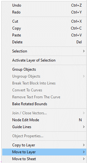
NOTE: Vcarve also has a 'layers' feature, which is very useful. It's very advantageous to separate the vectors for each toolpath into individual layers. To do this, you select each vector you'd use for a toolpath, right click, and select "move to layer". You can also change the color of specific layers, to make it more clear which tool will follow which path. That also makes it easy to select all vectors associated with each toolpath. However, remember to select all vectors in each layer when attempting to move the vectors, or else certain features might end up offset on the part.
¶ Previewing/Saving the Toolpath
Once the settings have been defined, we are ready to preview the toolpath to ensure the cut will be correct. Previewing is also useful to make sure you have all of the tabs placed properly.
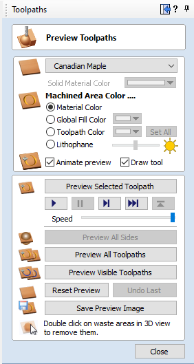
From there, click "Preview All Toolpaths". This will play out an animation of the entire job, and show what the material will look like after it has been cut.
If you change properties in the toolpaths, or move the vectors in the 2D view, make sure to:
- Recalculate the toolpaths
- Reset the preview, and re-run the preview
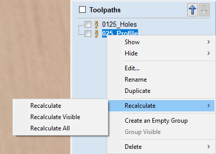
To recalculate the toolpaths, right click on your toolpath, go to the recalculate menu, and select recalculate all. If you don't recalculate the toolpaths, the Gcode will not be updated and won't represent the changes you made to the toolpath properties or vector positions.
The last step is to save the toolpath. Make sure to have the correct Post Processor selected: Laguna Swift CNC (mm) (*.mmg) if using the Laguna Swift.
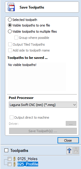
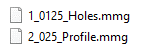
There are a few options to save it. The general rule of thumb is that there will be a separate file for each tool used on the job. As you can see in the attached screenshot there are two toolpaths, 0125_Holes, and 025_Profile. They are named this way to indicate which tool is used, and what sort of operation is being done. For 0125_Holes the toolpath will use a 0.125" O-flute end mill and will machine the holes in this specific part. The 025_Profile toolpath will use a 0.25" O-flute end mill, and will machine the inner and outer profiles of the part.
The last part of the naming convention is the job number, which specifies the desired order in which the toolpaths should be run. In the case of this example, the gcode should be saved as 1_0125_Holes, and 2_025_Profile. In general, the last thing that should run is the outer profile toolpath. This ensures that the part won't separate from the rest of the sheet while any of the other features are being cut. The order of any other toolpaths is somewhat less important, but should be ordered in such a way as to minimize the number of tool changes required.
If there are two toolpaths that use the same tool, it may be possible to save them both to a single file. For example, if there is a pocket and a profile toolpath, both using a 0.25" end mill, these toolpaths can be combined into one file. All saved toolpaths should be placed inside of a folder that is named relevant to the parts being machined. For example:
placed inside of a folder named after the subsystem/part being machined.
Once all of the toolpaths have been saved using the correct naming convention so as to indicate the type of bit being used and the order in which the jobs must be completed, the entire folder of gcode needs to be copied over to the flash-drive of the machine. Then, finally, the job is ready to run!
¶ Advanced Techniques
While making a toolpath is easy, taking full advantage of the properties and features of the machine is generally more difficult.
As stated earlier, the Swift has a vacuum bed. If the vacuum seal is broken, the part is likely to shift on the spoilboard as there will no longer be downward pressure onto the material. One possible way to prevent this from happening, is to avoid cutting completely through the material until the very last pass. So, if your material is ¼” (0.25 inches) thick, then create one set of toolpaths that leave anywhere from 0.005-0.02” (DOC = 0.230 – 0.245”), and a final toolpath that take out the remaining material. Of course, make sure to not remove the tabs.
This method would require an extra tool change for the final overall pass, but maintaining the vacuum pressure for the duration of the job is priceless.
Here are a few videos that go into the more advanced details of pocketing and profiling cuts.
Profile Toolpaths: https://www.youtube.com/watch?v=w8def6kuuLU
Pocket Toolpaths: https://www.youtube.com/watch?v=inMuJcB2IuQ
Spoil board Flow through: https://www.youtube.com/watch?v=IYYhdjF8JI8
¶ Quiz - Vcarve
- Where should the XY zero be defined?
- Top left
- Top Right
- Center
- Bottom left
- Bottom Right
- Where should the Z zero be defined?
- Material Surface
- Machine Bed
- What should the dimensions of the workspace be in Vcarve?
- 12" x 12"
- 12" x 24"
- Approximately equal to the sheet of material
- Slightly larger than the part being cut
- What file type do you export your part as from Onshape?
- .dwg
- .dxf
- After importing your vector files into Vcarve, what is the next step?
- Create a toolpath
- Preview toolpath
- Join the vectors
- Combine vectors
- What type of toolpath requires tabs?
- Profile
- Drill
- Texturing
- I should include a ramp on my profile toolpath.
- True
- False
- When should a pocket toolpath be used to cut the internal shapes of a part?
- Many, small internal pockets
- Few, large internal pockets
- If the properties of a toolpath are changed, or the vectors are moved on the workspace, what is the first thing that needs to be done?
- Recalculate the toolpaths
- Save the toolpaths
- Reset the toolpath Preview
- What is the correct Post Processor to use when saving toolpaths for the Laguna Swift?
- Laguna Swift Cut3d (mm)
- Shapeoko (mm)
- Laguna Swift CNC (mm)
- Which of the following is the correct format for a saved toolpath?
- 1_025_Profile
- 0125_Holes
- 3_ProfileCut
- 2_0125_Holes
- Which of the following is the last toolpath that should be run?
- Inner pocketing
- Mounting Holes
- Outer Profile
- If I'm cutting 6061 Alumimum, which tool settings should I use?
- 6061Al tool
- 5052Al tool
- Plastic
- Wood
- Should I double check that I'm using the correct tool settings for the material?
- Yes
- Seriously, Yes
- Yep
- Nah, I'm happy to replace the end mills that will inevitably break
- What is the easiest way to check if the tabs are in the correct locations?
- Preview the toolpath
- Just send it on the Laguna
¶ Skillset Verification
- Export DXF from Onshape
- Create new file/workspace in Vcarve
- Import DXF into Vcarve
- Join vectors
- Move vectors to required position in workspace
- Select vectors for toolpath
- Optimize settings for toolpaths
- Create and effectively place tabs
- Put toolpaths in correct order
- Preview toolpaths to ensure tabs are correct
- Save toolpaths with correct naming scheme
¶ Fixturing/Spoilboard
¶ Introduction
The most important facet of CNC routering is fixturing. Fixturing, or workholding, involves holding your material onto the machining bed. Fixturing is important for a few reasons:
- Preventing tool chatter
- This protects the tool from being damaged by the material
- Ensures a smooth material finish
- Preventing the material from moving
- Even small movements of the material could potentially ruin a part that requires high precision (press-fit bearings)
- Movements will also damage the tool, as it will no longer be cutting the desired amount of material in each pass
¶ Vacuum Fixturing with Spoilboard
As mentioned earlier, the Swift CNC uses vacuum fixturing. This means that there is a vacuum that pulls the air out from underneath the worktable/spoilboard and uses the pressure of the atmosphere to push the part down onto the spoilboard. This relies on a secure seal between the build table, the spoilboard, and the part. If there are any holes in the part, or if the spoilboard is uneven/pocketed, the effectiveness of the vacuum is drastically reduced. Because of this, we also use T-slot clamps on the material, to ensure it doesn’t move once the vacuum seal is broken.
The following videos outline the general process for placing the gaskets, and creating a spoilboard.
https://www.youtube.com/watch?v=sx8fAv5f8js Watch to ~6:15

This video shown earlier also outlines the steps to surface a spoilboard in Vcarve:
https://www.youtube.com/watch?v=IYYhdjF8JI8
It is imperative to work off a perfectly perpendicular surface to the spindle. The machine comes with a near perfect flat surface that is perpendicular to the spindle, commonly refered to as the worktable. It is important to never damage this, as any ridges could throw off the accuracy of the part or allow for air to flow where it is not meant to and breaking the vacuum seal. A spoil board (usually a piece of MDF between 3/4" and 1") is used to create a barrier between the top of the worktable and the material being cut. A spoil board is meant to protect the surface of the worktable and allow for the tool to cut into a little bit to ensure the piece is fully profiled out of the stock. If a tool goes into the spoil board isn't the end of the world, but that usually means that your Vcarve wasn't set up properly, or the machine was not zeroed properly. In certain cases, it is beneficial to machine slightly into the spoilboard, to make sure that the material is cleanly and completely cut through (makes deburring much easier). However, make sure to not go more than 0.015” into the spoilboard, as to not waste too much when the spoilboard has to be resurfaced. The less it cuts into the spoilboard, the better.
If it is a new spoilboard, you must take about 0.040” off from each side. This helps open up the MDF to get to the more pourous inside. MDF is basically a sandwich, with two dense layers on the top and bottom of the material, and less dense material in the middle. Either side of the MDF is surfaced to take out imperfections and allow air to flow through more easily, creating a great work top for using on the router.
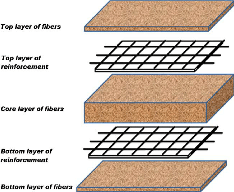
MDF is semi-porous material meaning an airflow can be created through the piece of wood. Thus, creating a vacuum to hold material to the table.
Keep in mind that:
F = PA
Force is equal to pressure multiplied by area, when we create a vacuum we are creating negative pressure on one side of the work piece, thereby using atmospheric pressure to force our parts to the table. As area increases, the force to hold the part to the worktable also increases, and the inverse is true as well. Less surface area on the part means not as much force to hold the part to the table. Keep this in mind when using a sole vacuum fixture solution.
¶ Callback
This is where the advanced technique discussed in the Vcarve section can be used. This technique is commonly referred to as onion-skinning, but our application is slightly different. The name comes from the thin layer that is leftover after the cut and is generally used as an alternative to tabs. It’s also more commonly used with wood. However, in our case, it would be used in conjunction with tabs to prevent both loss of vacuum and the shifting of parts. The key component of this technique is to have the depth of cut on the last pass be significantly smaller than the rest of the passes to ensure less stress is placed on the material, and there is a smaller chance of the material shifting while under load.
¶ Clamps
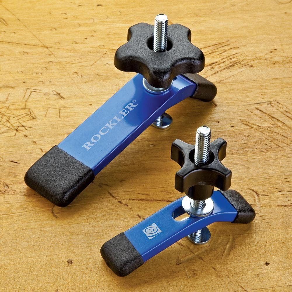
Another method of attaching large sheets to the worktable is using special T-slot Clamps. These devices are called T-slot clamps because they slide into T-slots on the worktable and they use a lever effect to clamp the work piece to the table. It is imperative that the user makes sure that the g-code is set up in a way that takes the clamps into account when programming the machine. It is common practice to put four (4) clamps on the corner of the stock that will be cut. This is useful when the user has a non-ordinary shape of flat stock to cut. The user will set down a spoil board, the work piece, and then clamp them both to the table using the T-slot clamps. This can be used on non-vacuum worktables as well, i.e. the smaller Laguna iQ that is in the shop.
With exceptionally large sheets additional holes might be needed to hold the work piece down to the spoil board. It would be wise to drill out small holes (#10 clearance holes for example) first in one operation, then adding brass or plastic screws to hold the part down to the spoil board to reduce the center of the material bowing. Both t-slot clamping and vacuum fixturing require a spoil board.
Here is a decent resource with more general information.
https://www.onsrud.com/articles/Fixturing-and-Routing-of-Plastics-with-CNC.asp
¶ Quiz
- When surfacing a new MDF spoilboard, how much material should be taken off?
- 0.004" - 0.00625"
- 0.040" - 0.0625"
- 0.025" - 0.040"
- 0.250" - 0.500"
- When re-surfacing an old MDF spoilboard, how much material should be taken off?
- 0.040" - 0.0625"
- 0.250" - 0.500"
- 0.010" - 0.020"
- If you are using the vacuum fixturing, should you also use T-slot clamps?
- Yes, they are a good backup and required once the vacuum seal breaks
- No, vacuum fixturing is enough
- What happens to the vacuum suction when the surface of the material has been cut through completly?
- The vacuum pressure is drastically reduced
- The vacuum pressure stays the same
- The vacuum pressure increases
- What types of fixturing solutions does the Laguna Swift have?
- Vacuum fixturing
- T-slots
- Rollers
- Why do both sides of a new MDF spoilboard need to be fly-cut to be used as a flow-through fixture/spoilboard? (select all that apply).
- It makes the spoilboard flat relative to the router gantry
- It hardens the surface of the MDF
- It tells the machine the dimensions of the work space
- It clears away the compressed fibers to allow air to flow through
¶ Skillset Verification
- Generate Gcode to resurface spoilboard
- Properly secure material to spoilboard/worktable
¶ Manual Operation/Control
¶ Introduction
Now that we understand Vcarve, and how to secure the part to the work table, it is time to power things up. Our lord and savior Router Bob has a great tutorial outlining all the basics of manual control that you will need.
Relevant time ranges are 4:55-7:53, and 10:47-End.
https://youtu.be/PsTxgi9HG0g?t=295

https://youtu.be/PsTxgi9HG0g?t=647
¶ Key points to look out for/Various notes:
- Powering on and off
- Home axes
- Manually moving axes (jogging)
- Changing speeds between high and low
- Changing movement options (continuous, step, distance)
- We almost exclusively use continuous
- Changing coordinate frames (machine/work frames)
- Set Origin/Zero point offset
- Manual and Automatic Z zeroing
- Make sure to test retraction of Auto tool touch off
- Changing thickness of puck
- Turning spindle on/off, changing speeds
- Almost never need to manually turn spindle on/off
- How to get RPM of spindle from number on display
The number on the inverter display is the spindle speed in units of Revolutions/Second. So, to get Revolutions/Minute, just multiply the number on the display by 60 (seconds/minute). For example, if the display says 300 RPS, that is equivalent to 18,000 RPM.
¶ Relevant Controller Keybinds

For clarity, if the keybind says Press/Hold next to a button, that means you press and hold that specific button and press the following button WHILE still holding down the previous button. After pressing both, release both buttons at the same time.
Important Keybinds:
Press/Hold Menu + On/Off
Press/Hold Menu + 0
Press/Hold Menu + 1-9
Menu - C.A.D. Thickness to change Puck height.
¶ Extra Videos
Movements: https://www.youtube.com/watch?v=BTi0W4Fez8s
Homing: https://www.youtube.com/watch?v=xctc3RKTAGI
Controller: https://www.youtube.com/watch?v=si5DCqJlnT8
¶ Quiz
- After turning the machine on, what must you do before jogging any of the axes?
- Home the Axes
- Zero X, Y, and Z
- Start the spindle
- Make sure the table is clear of tools/large objects, then Home the Axes
- What will happen if you press and hold the Menu button, then press the On/Off button?
- The work reference frame will change
- The spindle will start
- The automatic Z-touchoff will start
- The spindle will stop
- If there is the letter A next to the X, Y, Z on the left side of the controller screen, what does this mean?
- The machine is currently at the origin
- The machine is in a work coordinate frame
- The machine is in the machine coordinate frame
- The machine has an undefined origin
- If there is a number next to the X, Y, Z on the left side of the controller screen, what does this mean?
- The machine is currently at the origin
- The machine is in a work coordinate frame
- The machine is in the machine coordinate frame
- The machine has an undefined origin
- What do you think will happen if you press the XY->0 button when in the machine coordinate frame?
- The origin will be set
- Nothing, because we are in the machine frame
- What do you think will happen if you press the XY->0 button when in a work coordinate frame?
- The origin will be set
- Nothing, because we are in a work frame
- When you attach a new tool onto the spindle, and want to run the automatic Z-touchoff, what is the first thing you should do?
- Do a test run well above the part/spoilboard and touch the puck to the tool, to confirm the Z axis will stop
- Run the Z-touchoff procedure
- Nothing
¶ Skillset Verification
- Powering on and off
- Home axes
- Manually moving axes (jogging)
- Changing speeds between high and low
- Changing movement options (continuous, step, distance)
- Changing coordinate frames (machine/work frames)
- Set Origin/Zero point offset
- Manual and Automatic Z zeroing
- Turning spindle on/off, changing speeds
¶ Summary + Tool Changing/Running a job
¶ Introduction
Now that we understand all aspects of using the Laguna, it's time to actually run a job. You've saved all of your toolpaths into a folder named after the part, with the job number and tool diameter in the name of the each toolpath file. Then transferred the folder to the USB drive and plugged the drive back into the top corner of the controller. The process to actually run a file was outlined in one of the previous videos (Swift CNC Setup, 23:20 minute-mark).
Once the file is on the USB in the controller, it's time to properly secure the material to the work table/spoilboard. The process for this is outlined in the previous section.
¶ Zeroing
When the clamps are secure, it is time to Zero the axes. The X and Y zero should be placed in same place defined in Vcarve, generally the lower left corner. To do this, jog the spindle to the approximate lower left edge of the material, and press the XY->0 button.
Once the XY zero is set, do not change it, or move the material while the job is being run.
If you ever change the XY zero in between running separate toolpaths, or if the material shifts between jobs, the part will be ruined, as none of the holes/profiles will line up properly. Once this is set, you're ready to zero the Z. First, make sure the correct end mill is attached in the spindle, and securely fastened at the correct height relative to the collet face. Next, make sure to have your material securely fastened to the work table. If you are using the vacuum fixturing, make sure to turn on the pump when zeroing the Z axis. When the vacuum is turned on, it will pull the spoilboard and material towards the work table. If you have already zeroed the Z axis, it will no longer be valid when the material is pulled down.
¶ Coolant
Once the X, Y and Z axes have been zeroed, if you are cutting metal, the last step is to add a small amount of coolant/lubricant to the surface of the material. This is to ensure the bit stays cool, and to help the chips clear while the machine is cutting. However, make sure to avoid getting coolant onto the spoilboard. Since MDF is very pourous, it will absorb any liquids and expand, making it no longer a flat surface.
¶ Chip Clearing
The Laguna swift is also outfitted with an orange hood around the spindle. This hood is connected to a second vacuum, and is responsible for pulling the cut chips away from the part. This vacuum MUST be on when a job is running to prevent chip build up.
¶ Summary of steps:
- Load Gcode onto flashdrive from computer
- Plug flashdrive into controller
- Securely fasten material to router bed
- Make sure correct tool is in the spindle
- Zero X and Y axes
- Turn on table vacuum pump (if applicable)
- Zero Z-axis
- Select correct job/toolpath on the controller
- Turn on chip vacuum
- Ensure everything is clear on the worktable, and around the laguna
- Start program
Once again, our hero Router Bob is here with a great video summarizing a lot of the techniques we will use in our shop.
Example Job: https://www.youtube.com/watch?v=OEpApUx6JeU

In example job, Bob uses a few more 'advanced' techniques. First, he has a Rough cut and Finishing cut. The rough cut is a conventional cut that takes away 'most' of the material (in the example he leaves 0.03" with the allowance offset option). The final cut is a climb cut which takes away the remaining 0.03" of the profile, all in a single pass. This makes the final profile very clean. NOTE this is different from the onion-skin technique mentioned earlier.
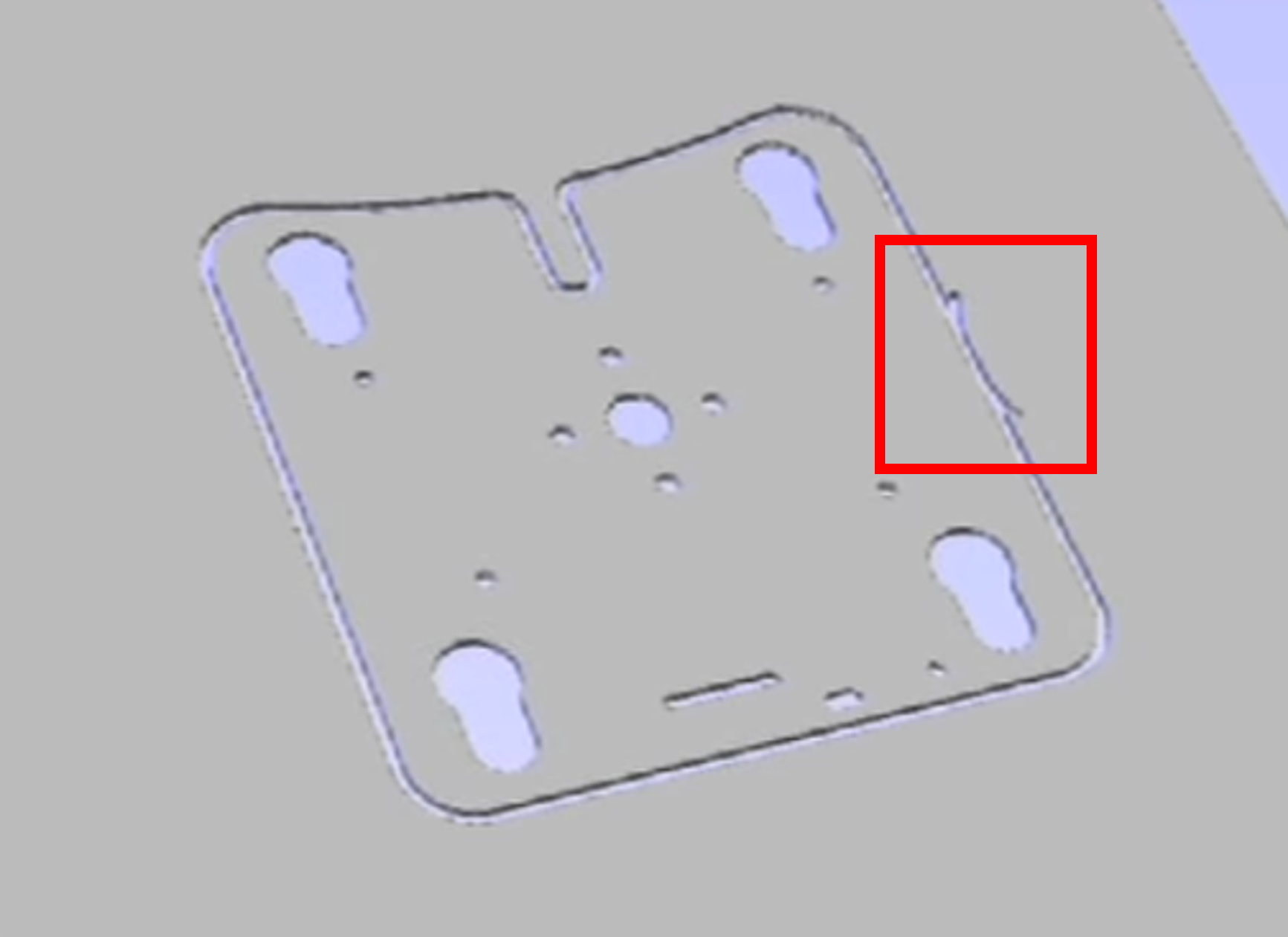
You might also notice the strange shape on side of the profile. This is known as a 'lead' and is used to both prevent the tool from idling against the edge of the part, and to doubly ensure the outside of the part has a smooth finish. All of these settings are adjustable in Vcarve, and while they weren't mentioned specifically in this wiki, they can be very useful for certain situations.
¶ Other Relevant Topics
Changing Tool: https://youtu.be/PsTxgi9HG0g?t=1004
Suppose while the job is running, you notice that the spindle seems to be travelling somewhat too fast, and would like to slow it down. Rather than stopping the job, adjusting the Vcarve, and reuploading the Gcode to the flashdrive, you can adjust the cut speed real time on the machine.
Adjusting Cut speed: https://www.youtube.com/watch?v=B7Khhb2YM8Q
Suppose that you need to stop the job for any reason, and potentially resume it later on, you can use a Break Point. When you press the Stop/Cancel on the controller, it will stop the job and prompt you to save a break point. This allows you to resume the job from that specific point in the program. Once you select that break point, you can also adjust the specific line of Gcode the job will resume at. Here is a video outlining the use of break points.
Break Points: https://www.youtube.com/watch?v=vLSHOKEAZPI
Suppose the XY origin was incorrectly defined in the program, or the XY origin was improperly set on the machine, it is possible for an Origin Error to occur when attempting to run a job. Here is a video outlining the problem and possible solutions.
Origin Error Fix: https://www.youtube.com/watch?v=DuPqQhKFnLs
For other general usage information:
User Guide: https://860860.app.netsuite.com/core/media/media.nl?id=1225326&c=860860&h=a350141f557e8b0faa1c&_xt=.pdf
¶ Final Notes
This page is by no means a comprehensive guide. While it generally covers most of the most key topics of CNC router use, there is significantly more information out there on the web. The Laguna Tools Youtube channel has a huge list of Vcarve and general machine usage tutorials. These tutorials discuss more of the advanced options of Vcarve as well as other machining tips and tricks. The tips outlined in this wiki are a good starting point for operation of the machine, but by no means the best way to do things. There are plenty of techniques and other options in Vcarve that can be utilized to produce better parts, and increase the safety of the overall operations.
¶ Tool Wear Tracking and Offsets
0250 bit - S/N 028F (-0.003")
¶ Quiz
- How far does Router Bob say to put the end of the flute away from the face of the spindle collet?
- I didn't watch that part of the video
- Flush with the face
- 1/16" Inch away
- 1/8" Inch away
- What is the maximum depth of cut for a 1/4" end mill in Aluminum?
- 1/4"
- 1/8"
- 1/16"
- 1/2"
- What is the maximum depth of cut for a 1/4" end mill in Plastic?
- 1/4"
- 1/8"
- 1/16"
- 1/2"
- What is the controller shortcut to load a break point?
- Press/Hold Run Pause/Delete and On/Off
- Press/Hold Run Pause/Delete and 1
- Press/Hold Menu + Run Pause/Delete
- Press/Hold Menu + 1
- How can the user change the slewing speed while a job is running?
- Press Y+ or Y-
- Press Stop/Cancel
- Press On/Off
- Press X+ or X-
- What materials require coolant be used to cut?
- Aluminum
- Plastic
- Wood
- If the machine is properly zeroed, and the material securely fastened, what should I do before starting the job? (select all that apply)
- Make sure the worktable is clear of potential obstructions
- Make sure those around are aware the machine will start moving
- Double check that I'm running the right job with the correct tool choice
- Be wearing safety glasses and hearing protection
¶ Skillset Verification
- Load Gcode onto flashdrive from computer
- Plug flashdrive into controller
- Securely fasten material to router bed
- Make sure correct tool is in the spindle
- Zero X and Y axes
- Turn on table vacuum pump (if applicable)
- Zero Z-axis
- Select correct job/toolpath on the controller
- Turn on chip vacuum
- Ensure everything is clear on the worktable, and around the laguna
- Start program